|
Representing Software Architectures For Large Scale
Systems:
The Layered Package Diagram
by Jeff Garland
President & CTO
CrystalClear Software, Inc
2001-Aug-10
Executive Summary
This paper will focus representing the architecture of
large-scale systems. UML has a rich set of primitives and
extensibility. While some authors have addressed tried to
address the use of UML for large-scale systems [1][2][3],
little has been written about good
representations for large-scale systems. This paper introduces
the layered package diagram, which has proven to be a useful view for
understanding the logical architecture of large-scale systems.
Problems for Modeling Large Scale Systems
Large-scale systems commonly come with a host of complications,
including:
- large amounts of source code (typically millions of lines)
- high complexity of interaction between components
- extensive use of off-the-shelf components
- use of multiple languages
- large numbers of developers (often hundreds, often geographically distributed)
- multiple persistence mechanism (files, relational databases, object databases)
- distribution of components over several hardware platforms
- high amounts of concurrency
Each of these attributes makes a common understanding of system
architecture amongst team members and stakeholders more difficult.
The architect faced with designing, managing development, and
communicating a large-scale system needs useful views of the
system. It is simply naive to believe that modeling all the
classes and methods of the system is a possible or useful way to
view the logical architecture. Typical UML references such as
The Unified Modeling Language User Guide [4] or UML Distilled
[5] will not provide much guidance.
Layered Package Diagram
The Basic Diagram
The layered package diagram is used as a central view to
represent a software system compile-time logical architecture.
This view can be used to communicate multiple system aspects
to different project stakeholders. As such, it is a nice
complement to other types of diagrams that describe other
aspects of the overall system architecture.
Traditional architecture diagrams often include a "layered view"
of the system. These are easy to "understand" views for
non-software participates. However, for the software developers
the layered view compactly represents a critical aspect of the
software logical architecture: build time dependencies.
The layered package diagram is an adaptation of the layer
diagram using UML is to group packages into "related layers".
This diagram is similar to the "Tiers View" suggested by Doug
Smith[6], except that the diagram does not attempt to explicitly
represent dependencies. However, by implication packages in
higher layers depend on lower layers but not the other way
around. Note that a higher layer package is not required
to depend on lower layer packages, but might.
Figure 1 provides an example of the layered package diagram. The
lowest layer consists of third party packages such as database
and user interface libraries. The second layer represent libraries
maintained by the project to simplify common programming tasks.
The third layer consists of packages that provide components
specific to the problem domain. Finally, the top layer provides
applications or components realized by combining the lower
layers.
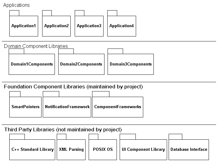
Figure 1: Layered Package Diagram
The example in Figure 1 does not represent the only possible set of
layers. A system may have more or less layers and different logical
relationships. The guiding principle, however, is that the upper
layers should depend on the lower layers and not vice versa.
Supplementing the layered package diagram with dependency
tables or other package level dependency mechanisms is valuable
so that the details of individual packages can be explored as
needed. The overview diagram can be used as a starting
point for more detailed dependency exploration.
Extending for other Purposes
Architects are frequently asked to provide managers and others
with auxiliary information about the system. The layered package
diagram can provide a handy framework for communicating such
information. For example, Figure 2 provides an example of the
layered package diagram annotated to describe the languages used
to implement various elements of the system. In addition, coloring
is used to highlight packages that have deliveries as part of the
first phase of development.
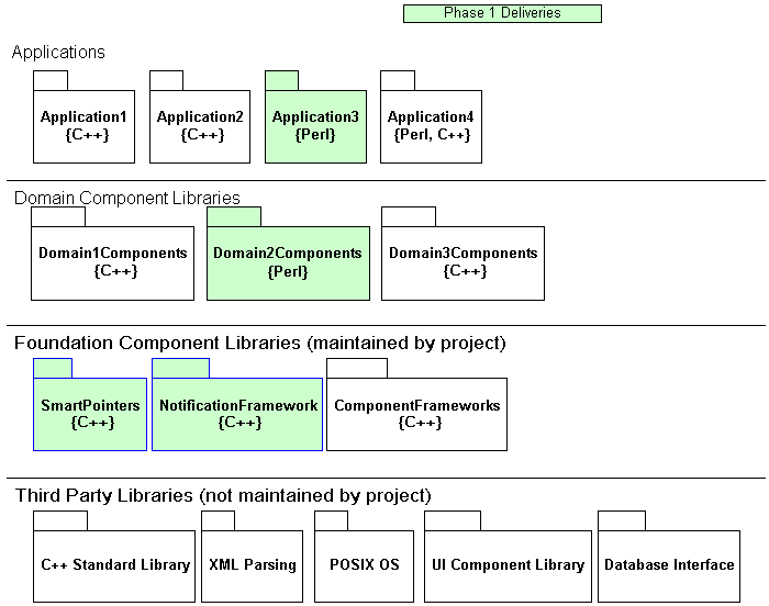
Figure 2: Layered Package Diagram with Language and Phasing Annotation
Advantages of the Layered Package Diagram
This diagram is useful for a number of reasons. First, it
provides a high level view of a large system. Second, it
provides an opportunity to see a view of many components and
basic dependency structure without a maze of dependency arrows.
From a development point of view, the expectation is that
packages at the bottom of the diagram will have many dependent
packages and hence instability in these packages can cripple
development in higher layers. In addition, the lower layers serve as
reusable assets that can be utilized for many types of software
projects.
One of the primary advantages of the layered package diagram is
that it can be used to communicate with different project
stakeholders with differing degrees of technical understanding.
Issues with the Layered Package Diagram
One problem with this diagram is the possible interpretation of
strict layering. Although it may seem to imply strict layering,
that is not the intent. That is, it is possible that a package
at the top of the diagram depends directly on the lowest level.
In reality, each layer is simply another package. Figure 3
provides a UML diagram that shows the semantics of the previous
layered view. Actually drawing the dependency structure in the
bigger view is cumbersome and detracts from the goals of the
view.
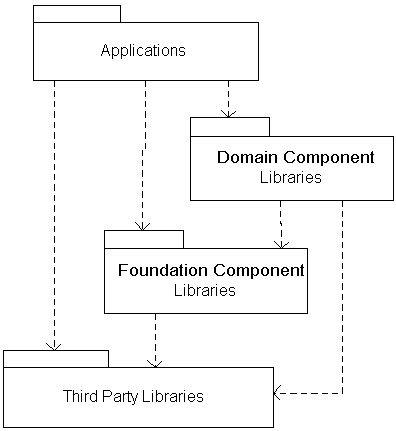
Figure 3: Dependency Semantics of Layered Package Diagram
One other problem with the diagram is the scalability of this
diagram. Even with the simplifications provided, in massive
systems with hundreds of packages other simplification
approaches must be used. For example, several layered
package diagrams may be required to represent the overview
of various logical system domains or application groups.
Each layered package diagram in this case only provides
a partial snapshot of the system structure.
Communication by Omission
The layered package diagram gains scalability for large systems
not by what it includes, but by what it represents implicitly.
The biggest problem with large-scale systems is the number of
elements and interconnections. Large numbers of components and
interconnections easily overwhelm both creators and consumers of
UML diagrams.
The layered package diagram gains scalability because the
location of a package on the diagram implies the dependency
semantics. This is very different from UML, which has explicit
representation for all elements and relationships.
Conclusions
This paper introduces the layered package diagram as
a central diagram for the representation of logical architecture
in large-scale systems. This is just one of several views
architectural views needed to effectively represent large-scale
system architectures. The layered package diagram scales to
larger systems by using positioning to describe dependencies
semantics instead of explicit notation. In addition, the
layered package diagram can be utilized to summarize
different aspects by use of coloring or labeling.
References
[1] P. Lago, P. Falcarin, "UML Requirements for Distributed Software
Architectures". In Proc. of the 1st International Workshop on Describing
Software Architecture with UML, (co-located with ICSE'2001), Toronto,
Canada, May 2001.
[2] C. Hofmeister, R. L. Nord, D. Soni,
Describing Software Architecture with UML, Proceedings
of the First Working IFIP Conference on Software Architecture.,
1999 IFIP, Published by Kluwer Academic Publishers.
[3] Kruchten, Philippe,
"Modeling Component Systems with the Unified Modeling Language",
A position paper presented at the International Workshop on
Component-Based Software Engineering., 1998.
[4] Booch, Grady, et. al., "The Unified Modeling Language User Guide",
Addison-Wesley, 1997.
[5] Fowler, Martin, et. al., UML Distilled, Second Edition,
"Addison-Wesley, 2000.
[6] Smith, Douglas, "Realizing Architecture through Realizing Use
Cases", Proceedings of UML World 2000, Jun 12, 2000, pp. 1131-1165.
© CrystalClear Software 2001, All Rights Reserved
|  Representing Software Architectures For Large Scale Systems